
During my stay at Lund University, I collaborated with Siemens Energy AB and other researchers on roughness-resolved, high-fidelity Large-Eddy Simulations (LES) of air flow over rough surfaces produced by Additive Manufacturing (AM) for turbine cooling applications.
Siemens Energy AB provided us with Inconel 939 samples produced with AM, which creates surfaces with random roughness, impacting heat transfer and pressure loss differently than traditional roughness (aka sand-grain roughness).
Using OpenFOAM 7, we performed LES simulations of air flows in rough pipes constructed from rough surfaces made with AM.
- In Garg et al. (2023), we performed LES simulations of turbulent air flows in rough pipes at a Reynolds number $\text{Re}=11700$ to reveal the influence of roughness parameters on turbulence, mainly the average roughness height and the effective slope, and to provide a rich database that will ease the development and assessment of future rough-wall models.
- In Garg et al. (2024), we performed LES simulations of turbulent air flows including heat transfer in rough pipes made of AM surfaces, with varying average roughness height and skewness values. As expected, we found that wall roughness affects heat transfer and momentum differently (the temperature rough wall function values are notably smaller than the momentum rough wall function ones).
The set of parameters used to characterised surface roughness is well identified in the literature, see for instance Kadivar et al. (2021).
I developed an open-source code in modern Fortran called STL_bend to:
- characterise the roughness properties of these planar AM surfaces
- and build cylindrical pipes from these surfaces for roughness-resolved CFD meshing.
This code is available on GitHub at https://github.com/CoffeeDynamics/STLRoughPipes.
Running The Code
Clone the repo and compile the code (requires gfortran).
$ git clone git@github.com:CoffeeDynamics/STLRoughPipes.git
$ cd STLRoughPipes
$ makeRun the provided example. The first parameter is the path to the STL file, the second is the merge tolerance factor (explained below).
$ cd run
$ ../bin/STL_bend.exe rough.stl 1e-3After a few seconds, you get the result.
STL file:                            rough.stl
Merge tolerance factor:              1.000000000000000E-03
Roughness factor:                    1.000000000000000E+00
Reading STL file... Done.
Computing statistics... Done.
Applying rotation around the X-axis... Done.
Writing ASCII file 'rough_new_ASCII.stl'... Done.
Writing binary file 'rough_new_binary.stl'... Done.

== STATISTICS OF THE SURFACE HEIGHT (before bending) ==
   Min roughness (R_min):               5.044040000000000E+00
   Max roughness (R_max):               7.692360000000000E+00
   Mean roughness (R_mean):             6.324590409642566E+00
   Arithmetic mean deviation (R_a):     4.075340714647828E-01
   Standard deviation (R_q):            4.933958337769399E-01
   Max roughness amplitude (R_z):       2.648320000000000E+00
   Max - Mean (R_p):                    1.367769590357434E+00
   Mean - Min (R_v):                    1.280550409642566E+00
   Skewness (s_k):                     -1.249407594122557E-01
Kurtosis (k_u): 2.381294337082244E+00As you can see, the code reads the STL file, computes some surface statistics, wraps the planar surface around the X-axis, and writes the result (a cylindrical pipe along the X-axis) in STL format (ASCII and binary encoding). Figure 1 shows the initial surface and the generated pipe seen in ParaView.
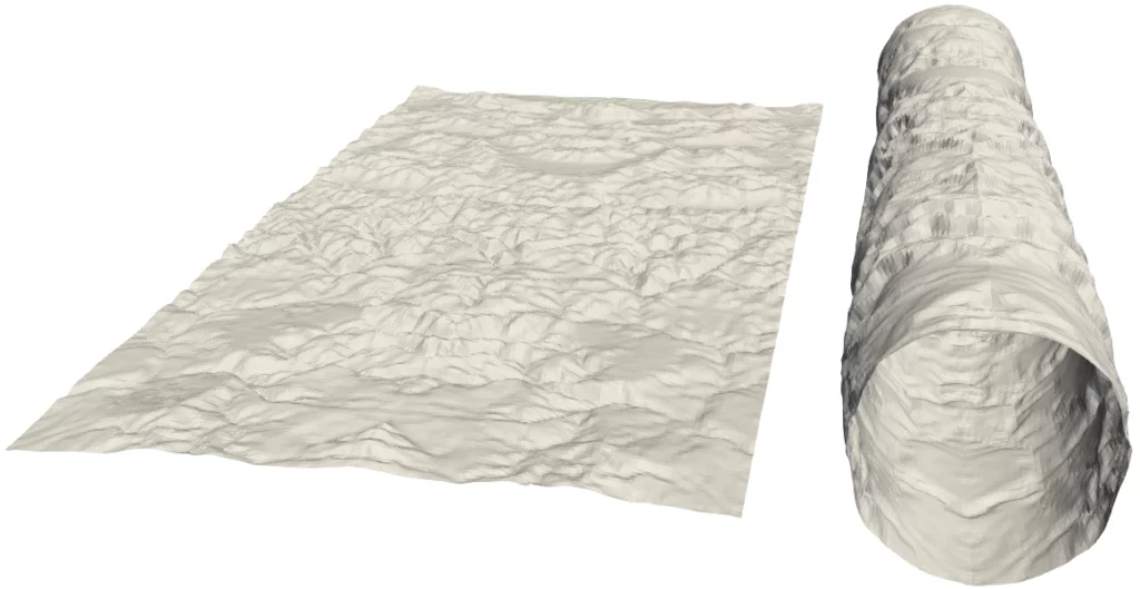
The next sections detail the different actions performed by STL_bend.
Computing Surface Roughness Properties
Figure 2 gives a representation of the planar surface before wrapping around the X-axis.
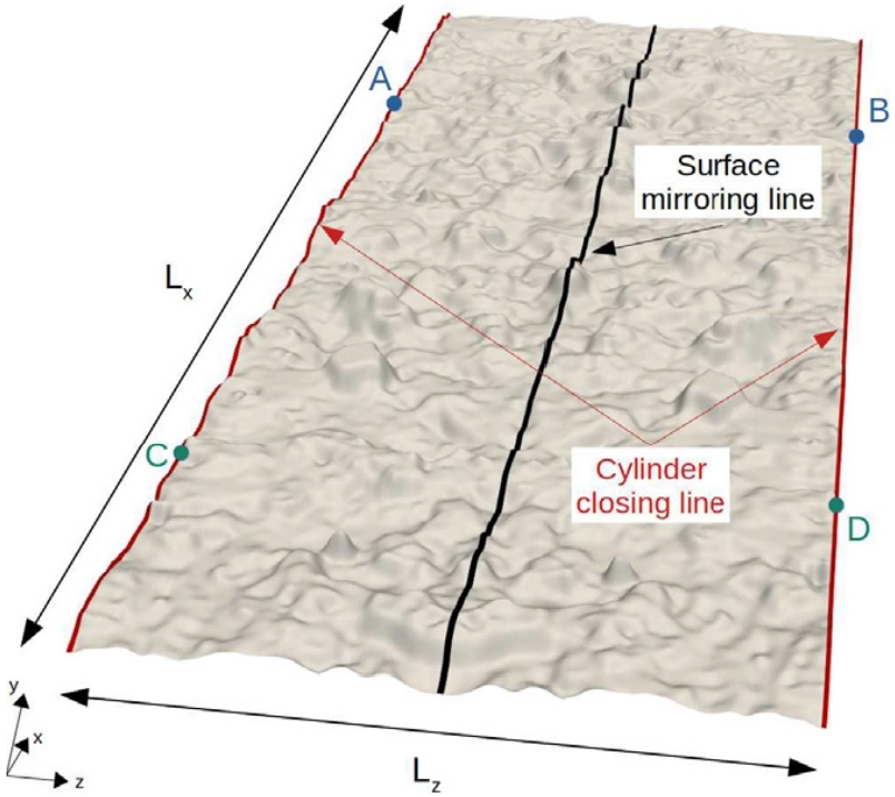
Here, the initial surface has already been mirrored w.r.t. to the black surface mirroring line (as is also the case in Fig. 1) in order to ease the closure of the future cylinder. This step is not performed by STL_bend, but can be easily done with various CAD or modeling software, e.g., Blender.
The surface height is along the Y-axis (in the actual STL_bend code, the surface height is along the Z-axis).
STL_bend computes the following surface roughness properties:
- Minimum roughness height, $R_\text{min}$ [m]
- Maximum roughness height, $R_\text{max}$ [m]
- Mean roughness height, $R_\text{mean}$ [m]
- Arithmetic mean deviation, $R_a$ [m]
- Root-mean-square roughness height (or standard deviation), $R_q$ [m]
- Maximum roughness amplitude, $R_y$ [m] ($R_z$ in the code)
- Maximum peak height above the mean line, $R_p$ [m]
- Maximum valley depth below the mean line, $R_v$ [m]
- Skewness, $s_k$ [-]
- Kurtosis, $k_u$ [-]
Their continuous and discrete expressions are given in Table 1.
| Para-meter | Continuous formulation | Discrete formulation |
|---|---|---|
| $R_\text{min}$ | $$\min y$$ | $$\min_{i=1,\dots,N}y_i$$ |
| $R_\text{max}$ | $$\max y$$ | $$\max_{i=1,\dots,N}y_i$$ |
| $R_\text{mean}$ | $$\dfrac{1}{L_xL_z}\int_0^{L_x}\int_0^{L_z}ydzdx$$ | $$\dfrac{1}{N}\sum_{i=1}^Ny_i$$ |
| $R_a$ | $$\dfrac{1}{L_xL_z}\int_0^{L_x}\int_0^{L_z}\left|y-R_\text{mean}\right|dzdx$$ | $$\dfrac{1}{N}\sum_{i=1}^N\left|y_i-R_\text{mean}\right|$$ |
| $R_q$ | $$\sqrt{\dfrac{1}{L_xL_z}\int_0^{L_x}\int_0^{L_z}\left(y-R_\text{mean}\right)^2dzdx}$$ | $$\sqrt{\dfrac{1}{N}\sum_{i=1}^N\left(y_i-R_\text{mean}\right)^2}$$ |
| $R_y$* | $$R_\text{max}-R_\text{min}$$ | $$R_\text{max}-R_\text{min}$$ |
| $R_p$ | $$R_\text{max}-R_\text{mean}$$ | $$R_\text{max}-R_\text{mean}$$ |
| $R_v$ | $$R_\text{mean}-R_\text{min}$$ | $$R_\text{mean}-R_\text{min}$$ |
| $s_k$ | $$\dfrac{1}{R_q^3}\int_{-\infty}^{+\infty}\left(y-R_\text{mean}\right)^3p(y)dy$$ | $$\dfrac{1}{R_q^3N}\sum_{i=1}^N\left(y_i-R_\text{mean}\right)^3$$ |
| $k_u$ | $$\dfrac{1}{R_q^4}\int_{-\infty}^{+\infty}\left(y-R_\text{mean}\right)^4p(y)dy$$ | $$\dfrac{1}{R_q^4N}\sum_{i=1}^N\left(y_i-R_\text{mean}\right)^4$$ |
STL_bend. Here, $N$ is the number of points in the STL file and the probability density function, $p(y)$, gives the probability of finding a point of height $y$.* The maximum roughness amplitude, $R_y$, is noted $R_z$ in the code.
Once the topographical information are computed, we can create the pipe.
Creating a Pipe
Figure 3 shows the transformation of a rough plane into a rough pipe.
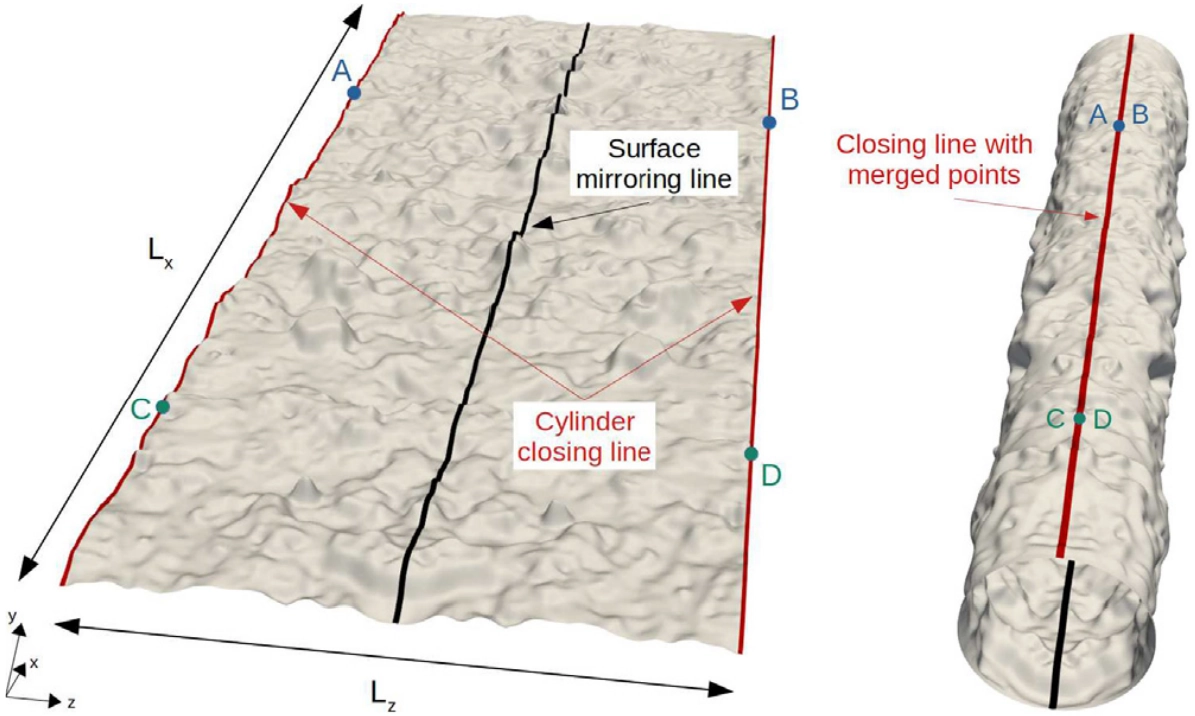
This operation consists of three steps:
- Mirroring the surface along the rotation axis (X-axis in Fig. 3) so that both red surface borders can be easily merged after rotation.
- Applying a rotation to all points of the STL file around the rotation axis (surface wrapping).
- Ensuring that the cylinder is properly closed along its closing line.
Step 1 has already been described in the previous section. We will now focus on steps 2 and 3.
Two options have been considered for the creation of rough cylinders. First, one can easily bend a planar surface to produce a cylinder using commercial or open-source CAD software. However, step 3 may be quite time-consuming. Indeed, the operation of merging points is typically achieved using an absolute threshold distance value such that two points whose separating distance is lower than the threshold value are considered to be merged. The immediate problem here is the difficulty, or even sometimes the impossibility, of determining an appropriate threshold value. To properly accomplish this operation, one then needs to make many attempts in a trial and error approach and carefully inspect the whole closing line to ensure both that no hole remains and that not too many points have been merged. Another concern about time consumption emerges when this procedure has to be performed a significant number of times, e.g., to gather statistics. Such repetitive actions then become tedious.
I have developed this code to reduce time consumption in the generation of these rough cylinders. It currently takes as arguments
- the path to the planar rough STL file,
- a tolerance factor to merge the points along the closing line of the cylinder,
- and an optional roughness factor to rescale the pipe surface roughness, if desired.
A tolerance factor of 0.001 usually leads to properly closed cylinders. This tolerance factor is inversely proportional to the surface resolution and, hence, requires particular attention. The ability to specify it in the command line constitutes a valuable ingredient of STL_bend by speeding up the process of building rough cylinders from rough planar surfaces.
Furthermore, the possibility to rescale the pipe surface roughness from the command line enables fast parametric studies of the influence of the roughness height for a given surface topography. STL_bend can then be invoked in a loop over STL files to process a large number of surfaces at once (batch mode).
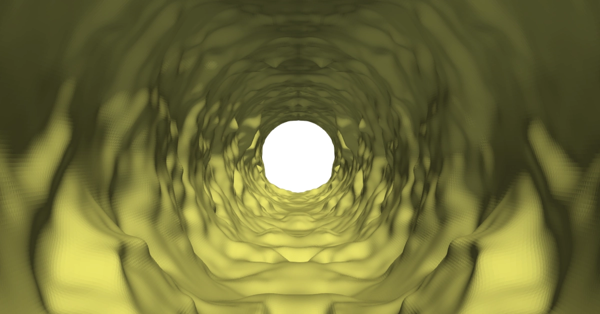
Once the pipe is created, you can import it in your meshing software to create inlet and outlet patches and meshes of the enclosed volume. I used snappyHexMesh, a meshing tool available in OpenFOAM. Figure 4 shows the example of such a roughness-resolved mesh.
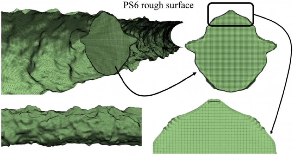
snappyHexMesh from a cylindrical rough pipe generated with STL_bend. Reproduced from Garg et al. (2024) with permission.Conclusion and Perspectives
STL_bend provides an easy way to create cylindrical rough pipes from planar rough surfaces. It is also possible to rescale the roughness height before creating the pipe via the optional second command line argument.
I plan to extend the code to create rough geometries of different shapes. Computing more surface statistics (e.g., effective slope) would be interesting. The possibility to prescribe (and not just compute) important quantities like skewness and kurtosis on the planar surface, before creating the pipe, would enable insightful parametric studies.
Leave a Reply
You must be logged in to post a comment.